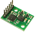
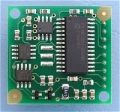
The CMPS11 is our 3rd generation tilt compensated compass.
Employing a 3-axis magnetometer, a 3-axis gyro and a 3-axis accelerometer.
A Kalman filter combines the gyro and accelerometer to remove the errors caused by tilting of the PCB.
The CMPS11 produces a result of 0-3599 representing 0-359.9 or 0 to 255.
The output of the three sensors measuring x, y and z components of the magnetic field, together with the pitch and roll are used to calculate the bearing, each of these components are also made available in there raw form.
The CMPS11 module requires a power supply at 3.6 - 5v and draws a nominal 25mA of current.
A choice of serial or I2C interfaces are provided.
Voltage - 3.6v-5v
Current - 35mA Typ.
Resolution - 0.1 Degree
Accuracy - Better than 2%. after calibration
Signal levels - 3.3v, 5v tolerant
I2C mode - up to 100khz
Serial mode - 9600, 19200, 38400 baud
| I2C mode |
Serial mode |
|
3.6v-5v
SDA
SCL
Mode
Factory use
0v Ground
|
 |
3.6v-5v
Tx
Rx
Mode
Factory use
0v Ground
|
|
To enter the I2C mode of operation leave
the mode pin unconnected |
To enter the serial mode of operation
connect the mode pin to ground |
The Factory use pin is for our internal testing only, this pin should remain unconnected.
PCB Drilling Plan
The following diagram shows the CMPS11 PCB mounting hole positions.