Overview
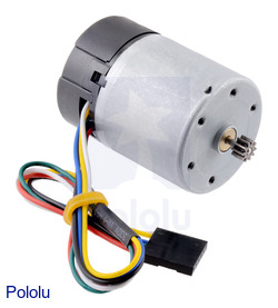
This motor with integrated 64CPR (counts per revolution) quadrature encoder is intended as a replacement motor and encoder for our 37Dmm metal gearmotors. The 2mm output shaft has a non-removable pinion gear that works with all of our 37Dmm gearmotor gearboxes. Note that we do not sell the 37Dmm gearboxes separately, but if you have a gearmotor with a damaged motor or encoder (or if you want to effectively add an encoder to a version without an encoder), you can transfer the gearbox to this replacement motor.
The motor has a diameter of 34.5mm (1.36in) and a length of approximately 44mm (1.7in) from the top of the motor can to the bottom of the encoder. The top of the motor has six mounting holes evenly spaced around the outer edge threaded for M2.5 screws. These mounting holes form a regular hexagon, with the center of each hole located 13mm from the center of the output shaft.. The mounting holes have a depth of approximately 3.5mm.
Pinion Gear Specs
- Metric with module m = 0.5
- Number of teeth: 10
- Face thickness: 4mm
- Pressure angle: 20°
- Gear position: 9mm from top of motor to top of gear
As of 24 December 2018, we have switched to using a more durable, alloy steel pinion gear with this motor. Units shipped before this date had copper pinion gears.
Gearmotor Options
You will typically want to combine this motor with a gearbox to give it a more appropriate combination of torque and speed (without a gearbox, it offers very high speed with very low torque). Our 37D mm line of metal gearmotors consist of this motor combined with different gearboxes. We do not carry the gearboxes by themselves, so unless you are looking at this as a replacement motor for a compatible gearbox you already have, we strongly recommend you consider getting a preassembled gearmotor with the gear ratio that best suits your project requirements.
Note: Stalling or overloading gearmotors can greatly decrease their lifetimes and even result in immediate damage. Stalls can also result in rapid (potentially on the order of seconds) thermal damage to the motor windings and brushes; a general recommendation for brushed DC motor operation is 25% or less of the stall current.
This motor is intended for use at 12V, though in general, these kinds of motors can run at voltages above and below the nominal voltage (this motor can begin rotating at voltages as low as 1V). Lower voltages might not be practical, and higher voltages could start negatively affecting the life of the motor.
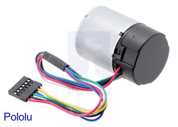
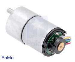
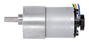
This motor is functionally identical to the previous version we carried without end caps (it is the same motor and encoder). The black plastic end cap is easily removable if you need to access the encoder or want to slightly reduce the overall motor size, but there is a little bit of base plastic that will remain, as can be seen in the pictures below that show this motor combined with a gearbox:
 |
37Dmm metal gearmotor with 64CPR encoder (with end cap removed). |
|---|
Using the Encoder
A two-channel Hall effect encoder is used to sense the rotation of a magnetic disk on a rear protrusion of the motor shaft. The quadrature encoder provides a resolution of 64 counts per revolution of the motor shaft when counting both edges of both channels. To compute the counts per revolution of the gearbox output, multiply the gear ratio by 64. The motor/encoder has six color-coded, 8³ (20cm) leads terminated by a 1#215;6 female header with a 0.1³ pitch, as shown in the main product picture. This header works with standard 0.1³ male headers and our male jumper and precrimped wires. If this header is not convenient for your application, you can pull the crimped wires out of the header or cut the header off. The following table describes the wire functions:
| Color |
Function |
| Red |
motor power (connects to one motor terminal) |
| Black |
motor power (connects to the other motor terminal) |
| Green |
encoder GND |
| Blue |
encoder Vcc (3.5 - 20V) |
| Yellow |
encoder A output |
| White |
encoder B output |
The Hall sensor requires an input voltage, Vcc, between 3.5 and 20V and draws a maximum of 10mA. The A and B outputs are square waves from 0V to Vcc approximately 90° out of phase. The frequency of the transitions tells you the speed of the motor, and the order of the transitions tells you the direction. The following oscilloscope capture shows the A and B (yellow and white) encoder outputs using a motor voltage of 12V and a Hall sensor Vcc of 5V:
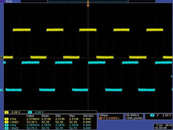 |
Encoder A and B outputs for 37Dmm metal gearmotor with 64CPR encoder (motor running at 12V). |
|---|
By counting both the rising and falling edges of both the A and B outputs, it is possible to get 64 counts per revolution of the motor shaft. Using just a single edge of one channel results in 16 counts per revolution of the motor shaft, so the frequency of the A output in the above oscilloscope capture is 16 times the motor rotation frequency.
Selecting the Right Gearmotor
We offer a wide selection of metal gearmotors that offer different combinations of speed and torque. Our metal gearmotor comparison table can help you find the motor that best meets your project#8217;s requirements.