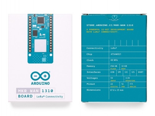
The Arduino MKR WAN 1310 board provides a practical and cost effective solution to add LoRa® connectivity to projects requiring low power. This open source board can be connected to: Arduino Create, to your own LoRa® network using the Arduino Pro Gateway for LoRa®, to existing LoRaWAN infrastructure like The Things Network, or even to other boards using the direct connectivity mode.
The MKR WAN 1310, brings in a series of improvements when compared to its predecessor, the MKR WAN 1300. While still based on the Atmel SAMD21 low power processor, the Murata CMWX1ZZABZ LoRa® module, and the MKR family’s characteristic crypto chip (the ECC508), the MKR WAN 1310 includes a new battery charger, a 2MByte SPI Flash, and improved control of the board’s power consumption.
The latest low power architecture has considerably improved the battery life on the MKR WAN 1310. When properly configured, the power consumption is now as low as 104uA! It is also possible to use the USB port to supply power (5V) to the board; run the board with or without batteries - the choice is yours.
Data logging and other OTA (Over The Air) functions are now possible since the inclusion of the on board 2MByte Flash. This new exciting feature will let you transfer configuration files from the infrastructure onto the board, create your own scripting commands, or simply store data locally to send it whenever the connectivity is best. Whilst the MKR WAN 1310’s crypto chip adds further security by storing credentials certificates in the embedded secure element.
These features make it the perfect IoT node and building block for low power wide area IoT devices.
You can find here your board warranty information.
OSH: Schematics
The MKR WAN 1310 is open-source hardware! You can build your own board using the following files:
EAGLE FILES IN .ZIPSCHEMATICS IN .PDFFRITZING IN .FZPZ
Pinout
The pinout in PNG format will be availabe next week!
Antenna
When purchased at the Arduino Store, the MKR WAN 1310 comes bundled with an antenna that can be attached to the board using the existing micro UFL connector. It is possible to use other antennas using the appropriate pigtail.
When purchasing a different antenna than the one provided (or when making your own), please check that it is tuned for the frequency band in use in the LoRa® / LoRaWAN range (433/868/915 MHz). Also avoid placing your antenna in parallel to a ground plane like a large metallic surface.
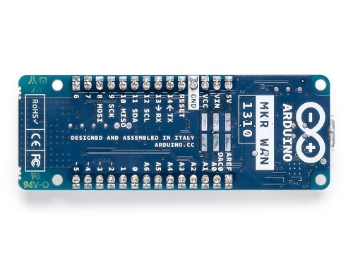
Batteries, Pins and board LEDs
- Battery capacity: rechargeable Li-Ion, or Li-Po. Please make sure the battery connector suits your battery.
- Battery connector: The connector is of type JST S2B-PH-SM4-TB(LF)(SN).
- Mating connector is JST PHR-2
- Vin: This pin can be used to power the board with a regulated 5V source. If the power is fed through this pin, the USB power source is disconnected. This is the only way you can supply 5v (range is 5V to maximum 6V) to the board not using USB. This pin is an INPUT.
- 5V: This pin outputs 5V from the board when powered from the USB connector or from the VIN pin of the board. It is unregulated and the voltage is taken directly from the inputs.
- VCC: This pin outputs 3.3V through the on-board voltage regulator. This voltage is 3.3V if USB or VIN is used and equal to the series of the two batteries when they are used
- LED ON: This LED is connected to the 5V input from either USB or VIN. It is not connected to the battery power, thus minimizing the impact on battery usage. It is therefore normal to have the board properly running on battery power without the LED ON being lit.
- Onboard LED: On MKR WAN 1310 the onboard LED is connected to D6.
| Microcontroller |
SAMD21 Cortex-M0+ 32bit low power ARM MCU (datasheet) |
| Radio module |
CMWX1ZZABZ (datasheet) |
| Board Power Supply (USB/VIN) |
5V |
| Secure Element |
ATECC508 (datasheet) |
| Supported Batteries(*) |
rechargeable Li-Ion, or Li-Po |
| Circuit Operating Voltage |
3.3V |
| Digital I/O Pins |
8 |
| PWM Pins |
12 (0, 1, 2, 3, 4, 5, 6, 7, 8, 10, A3 - or 18 -, A4 -or 19) |
| UART |
1 |
| SPI |
1 |
| I2C |
1 |
| Analog Input Pins |
7 (ADC 8/10/12 bit) |
| Analog Output Pins |
1 (DAC 10 bit) |
| External Interrupts |
8 (0, 1, 4, 5, 6, 7, 8, A1 -or 16-, A2 - or 17) |
| DC Current per I/O Pin |
7 mA |
| CPU Flash Memory |
256 KB (internal) |
| QSPI Flash Memory |
2MByte (external |
| SRAM |
32 KB |
| EEPROM |
no |
| Clock Speed |
32.768 kHz (RTC), 48 MHz |
| LED_BUILTIN |
6 |
| USB |
Full-Speed USB Device and embedded Host |
| Antenna gain |
2dB (bundled antenna at the Arduino Store) |
| Carrier frequency |
433/868/915 MHz |
| Working region |
EU/US (confirmed) for other countries, please confirm the viability of using the radio spectrum. |
| Length |
67.64 mm |
| Width |
25 mm |
| Weight |
32 gr. |